
An dieser Stelle haben wir Informationen über die elektrischen Einstellmethoden und Vorgehensweisen zusammengestellt, die Ihnen bei der Einstellung und Kalibrierung Ihres Tonbandgerätes behilflich sein können. Wir gehen davon aus, dass Sie ein gewisses Maß an Fachkenntnissen besitzen und sich an die Service-Anleitung des jeweiligen Herstellers halten.
Erforderliche Messgeräte und Werkzeuge:
– AC-Voltmeter (Frequenzbereich wenn möglich bis max. 20 kHz)
– Tonfrequenz-Generator (auch als PC-Software)
– Frequenzmessgerät
– Kopfentmagnetisierungs-Drossel
– Zweikanal-Oszilloskop
– Reinigungstupfer und 91%iger Alkohol
– Azimuth Alignment Tape, Speed and Flutter Test Tape, Calibration Level Tape, Multifrequency Calibration Tape
– Leeres Tonband
Zusätzliche Geräte:
– Verzerrungsanalysator
– Spektrumanalysator
– Pink & White Noise Generator
– Wow & Flutter Messgerät
Vorbereitung
Stellen Sie sicher, dass die Mechanik einwandfrei funktioniert. Nur wenn das Band richtig transportiert wird, ist eine Einstellung der Wiedergabe und Aufnahme möglich. Der Aufnahme- und Wiedergabekopf, die Andruckrollen und Antriebswellen, sowie alle Bandführungen sollten gereinigt und entmagnetisiert werden, um eine Beschädigung und Anlöschung des Test Tapes zu vermeiden.
Die Kalibrierungsschritte sollten in der folgenden Reihenfolge durchgeführt werden:
1. Wiedergabe-Einstellungen
1.1. Bandgeschwindigkeit
Für die Messung und Justierung der Bandgeschwindigkeit empfehlen wir die entsprechenden Speed and Flutter Test Tapes aus unserem Online Shop.
Das folgende Video zeigt eine Beispielmessung mit dem Speed and Flutter Test Tape, ¼″, 15 ips (38,1 cm/s), 3000 Hz, 3 Min., Art.-Nr. 76794. Der gemessene Wow & Flutter-Wert erreicht 0,011 % nach JIS.
Anmerkung: Die reproduzierte Frequenz hängt in einem gewissen Grad von der Bandspannung bzw. vom Anpressdruck auf den Wiedergabekopf ab. Das bedeutet, dass selbst dann, wenn die Bandgeschwindigkeit korrekt ist, eine vom Soll-Wert geringfügig abweichende Frequenz gemessenen werden könnte.
1.2. Pegeleinstellung der Wiedergabeverstärker
Um das richtige Calibration Level Tape für Ihr Tonbandgerät auszuwählen, sollten Sie herausfinden, welcher magnetische Fluss (nWb/m) für Ihr Tonbandgerät als Bezugswert (0 dB) vom Hersteller definiert wurde. Schauen Sie bitte in der Service-Anleitung nach.
Nehmen wir an, der Hersteller hat einen magnetischen Fluss von 250 nWb/m als Bezugswert definiert. Meistens steht in der Service-Anleitung dann: „250 nWb/m = 0 dB“. Bei 19 cm/s (7,5 ips) wäre das Calibration Level Tape, ¼“, 7.5 ips (19,05 cm/s), 1000 Hz, 250 nWb/m (DIN), 3 Min., Art.-Nr. 76363 für die Pegeleinstellung die richtige Wahl. Stellen Sie den Wiedergabeverstärker auf eine VU-Meter Anzeige von 0 ein – immer unter Last gemessen. Der Wert des Leitungswiderstandes (parallel am Ausgang, bzw. am Millivoltmeter anzuschließen) steht in der Service-Anleitung. Bei manchen STUDER-Geräten beträgt dieser 600 Ohm, bei anderen Tonbandgeräten, wie z.B. SONY liegt dieser bei 100 kOhm.
Bietet Ihr Tonbandgerät die Möglichkeit den Wiedergabepegel für jede Bandgeschwindigkeit separat einzustellen, dann wiederholen Sie den Vorgang mit dem entsprechenden Calibration Level Tape.
Anmerkung: Möchten Sie z.B. ein Tonbandgerät bei dem 320 nWb/m als 0 dB definiert sind, mit einem 250 nWb/m-Tape einstellen, dann soll das VU-Meter -2,14 dB anzeigen. Sie könnten den Sachverhalt hier leicht nachvollziehen: Audio-Pegelrechner.
Ein sehr praktisches Calibration Multi-Level Tape mit allen gängigen ANSI- und DIN-Levels finden Sie hier: Calibration Multi-Level Tape, ¼“, 7.5 ips (19,05 cm/s), 3 ANSI & 3 DIN Levels, 10 Min., Art.-Nr. 76389.
1.3. VU-Meter einstellen
Die Vorgehensweise wird in der jeweiligen Service-Anleitung beschrieben.
1.4. Wiedergabekopf-Spalteinstellung (Azimut)
MONO-Tonbandgeräte
Schalten Sie das Tonbandgerät auf die höchste Bandgeschwindigkeit. Starten Sie das entsprechende Azimuth Alignment Tape. Schließen Sie das Millivoltmeter an den Ausgang an. Verändern Sie die Spaltstellung des Wiedergabekopfs während der Wiedergabe solange bis ein Maximum der Ausgangspannung erreicht ist, wobei gleichzeitig die Pegelschwankungen ein Minimum betragen.
STEREO-Tonbandgeräte
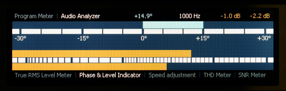
Schließen Sie den linken Kanal des Tonbandgeräts an die vertikale Ablenkung und den rechten Kanal an die horizontale Ablenkung des Oszilloskops an und schalten Sie den X-Y Modus ein. Starten Sie das entsprechende Azimuth Alignment Tape. Für 38 cm/s (15 ips) empfehlen wir das Azimuth Alignment Tape, ¼″, 15 ips (38,1 cm/s), 1 kHz 10 kHz 16 kHz, 6 Min., Art.-Nr. 76564.
Der Wiedergabekopf sollte so justiert sein, dass bei allen Frequenzen eine um 45° geneigte Diagonallinie von links unten nach rechts oben erzeugt wird.
Anmerkung: Abweichungen im Azimut bei der Wiedergabe oder Aufnahme-Wiedergabe-Kombination wirken sich mit abnehmender Wellenlänge (bei höheren Frequenzen) zunehmend als Phasenfehler aus – aus der Linie wird eine Ellipse, die bei 90° Phasendifferenz zu einem Kreis wird. Diese führen zu Pegelverlusten, deren Höhe hier sehr genau ermittelt werden kann: Berechnung der Spaltneigungsdämpfung.
Je nach Typ des verwendeten Referenzbandes können geringe Abweichungen zwischen den verschiedenen Geschwindigkeiten auftreten. In diesem Fall sollte der endgültige Azimutabgleich mit der bevorzugten Bandgeschwindigkeit vorgenommen werden.
Bei allen Azimut-Einstellungen sollten Spulen mit gleichem und möglichst großem inneren Kern verwendet werden.
Unten sehen Sie die Lissajou’sche Figur (Oszilloskop im X-Y Modus) beim Abspielen des Azimuth Alignment Tape, ¼″, 15 ips (38,1 cm/s), 1 kHz 10 kHz 16 kHz, 6 Min., Art.-Nr. 76564.
1.5. Wiedergabe-Frequenzgangabgleich
Hierfür benutzen Sie bitte die entsprechenden Multifrequency Calibration Tapes aus unserem Sortiment.
Fringing-Effekt: Beim Abspielen eines Vollspur-Testbandes mit Spurbreiten von 2 mm oder 1 mm, wie bei ½-Spur- oder ¼-Spur-Tonbandgeräten, findet wegen der seitlichen Einstreuung in das magnetische System des Wiedergabekopfs eine Anhebung der tiefen Frequenzen statt. Dies sollte mit Hilfe der entsprechenden Fringing-Werte korrigiert werden. Die Werte erhalten Sie gerne auf Anfrage. Für die Einstellung von Vollspur-Tonbandgeräten werden keine Korrekturwerte benötigt.
2. Aufnahme-Einstellungen
2.1. Pegeleinstellung der Aufnahmeverstärker (Vorabgleich)
Die Vorgehensweise wird in der jeweiligen Service-Anleitung beschrieben.
2.2. Kontrolle der Oszillator-Frequenz
Legen Sie ein neuwertiges und leeres Band auf und starten Sie die Aufnahme. Messen Sie die Oszillator-Frequenz an dem entsprechenden Messpunkt laut Service-Anleitung. Liegt die Frequenz außerhalb der Toleranzgrenze, muss der Oszillator nachjustiert werden.
2.3. Aufnahmekopf-Spalteinstellung (Azimut)
MONO-Tonbandgeräte
Schalten Sie das Tonbandgerät auf die höchste Bandgeschwindigkeit und schließen Sie den Tonfrequenz-Generator an den Eingang. Stellen Sie den Pegel auf ca. 10 dB unter dem Bezugspegel und die Frequenz auf 10 kHz ein.
Schließen Sie das Millivoltmeter an den Ausgang. Legen Sie ein neues und leeres Band auf und starten Sie die Aufnahme. Justieren Sie den Aufnahmekopf auf maximalen Ausgangspegel.
STEREO-Tonbandgeräte
Schalten Sie das Tonbandgerät auf die höchste Bandgeschwindigkeit und schließen Sie den Tonfrequenz-Generator parallel an die beiden Eingängen an. Stellen Sie den Pegel auf ca. 10 dB unter dem Bezugspegel und die Frequenz auf 10 kHz ein.
Legen Sie ein neues und leeres Band auf und starten Sie die Aufnahme.
Schließen Sie den linken Kanal des Tonbandgeräts an die vertikale Ablenkung und den rechten Kanal an die horizontale Ablenkung des Oszilloskops an und gleichen Sie den linken und rechten Signalpegel an. Schalten Sie den X-Y Modus ein. Justieren Sie den Aufnahmekopf bis Sie eine um 45° nach rechts geneigte Diagonallinie beobachten können.
Wiederholen Sie die Einstellung bei 16 kHz.
Wichtiger Hinweis: Der physische und der „elektrische“ Kopfspalt des Aufnahmekopfes sind nicht in der gleichen Position; der Versatz hängt von der Stärke des Vormagnetisierungsstroms ab. Aus diesem Grund muss die Azimutkorrektur nach der endgültigen Einstellung der Vormagnetisierung nochmals durchgeführt werden.
2.4. Vormagnetisierung
Die Einstellung der Vormagnetisierung stellt ein Kompromiss zwischen folgenden Parametern dar: Verzerrungsgrad, Frequenzgang, Modulationsrauschen und Aussteuerungsgrad.
Bei dieser Einstellung wird der Vormagnetisierungsstrom (bei konstantem NF-Signal) solange über das Empfindlichkeitsmaximum des entsprechenden Bandes erhöht, bis die NF-Ausgangsspannung ihr Maximum überschritten hat und um einen bestimmten Wert abgesunken ist.
Speisen Sie in den Eingang ein NF-Signal (10 kHz, 20 dB unter dem Bezugspegel) ein. Legen Sie ein leeres Band ein und starten Sie die Aufnahme.
Stellen Sie den Bias-Regler zuerst ganz nach links und drehen Sie langsam vom linken Anschlag im Uhrzeigersinn bis das Ausgangsignal während der Aufnahme sein Maximum erreicht hat. Notieren Sie den Wert und drehen Sie den Einstellregler weiter im Uhrzeigersinn (der Vormagnetisierungsstrom steigt) bis die Ausgangsspannung um den vom Band-Hersteller empfohlenen Wert gesunken ist. Diesen finden Sie in den technischen Daten des Bandes.
Wichtiger Hinweis: Bias-Parameter auf annähernd dieselben Werte für alle Kanäle einstellen.
2.5. Aufnahme-Pegeleinstellung kontrollieren und nachjustieren
Beachten Sie bitte hierzu die Vorgehensweise in der jeweiligen Service-Anleitung.
Falls eine starke Veränderung der Kopfspaltneigung erforderlich war, muss die Einstellung des Aufnahmepegels wiederholt werden!
2.6. Aufnahme-Frequenzgangabgleich
Beachten Sie bitte hierzu die Vorgehensweise in der jeweiligen Service-Anleitung.
Anmerkung: Bei vielen Heimtonbandgeräten und bei den meisten Cassetten Decks ist die Einstellung der Höhenanhebung im Aufnahmeverstärker vom Hersteller fest vorgegeben. Es besteht keine Möglichkeit die Höhen durch einen Trimmerpotentiometer zu verändern bzw. fein einzustellen. In diesem Fall wird der Frequenzgang mit Hilfe der Vormagnetisierung (Bias) eingestellt. Die meisten Einweisungen empfehlen einen tiefen Ton (meist 400 Hz) und einen hohen Ton (meist 10 kHz) auf einen gleichen Pegel bei der Aufnahme einzustellen – immer bei -20 dB. Dadurch wird der Frequenzgang bestmöglich „geglättet“ – auch wenn der Klirrfaktor dadurch nicht immer sein Optimum erreicht.
Weitere Test und Einstellungen
Wenn Sie über einen Verzerrungsanalysators verfügen, dann könnten Sie die Verzerrung auf ein Minimum einstellen.
Allgemeine Hinweise
Bitte lagern Sie Ihre Test Tapes kühl und trocken – am besten bei 19° C bis 23° C und 50 % relativer Luftfeuchtigkeit und nicht in der Nähe von starken Magnetfeldern. Beachten Sie bitte, dass sich die Test Tapes bei häufigem Gebrauch abnutzen und im Laufe der Zeit an Genauigkeit verlieren.
Zu Ihrem Schutz wurden alle Videos ohne Audiospur aufgenommen.